Wiring & Schematics
System diagram
Edit this project interactively in Cirkit Designer.
The controller is a development board with:
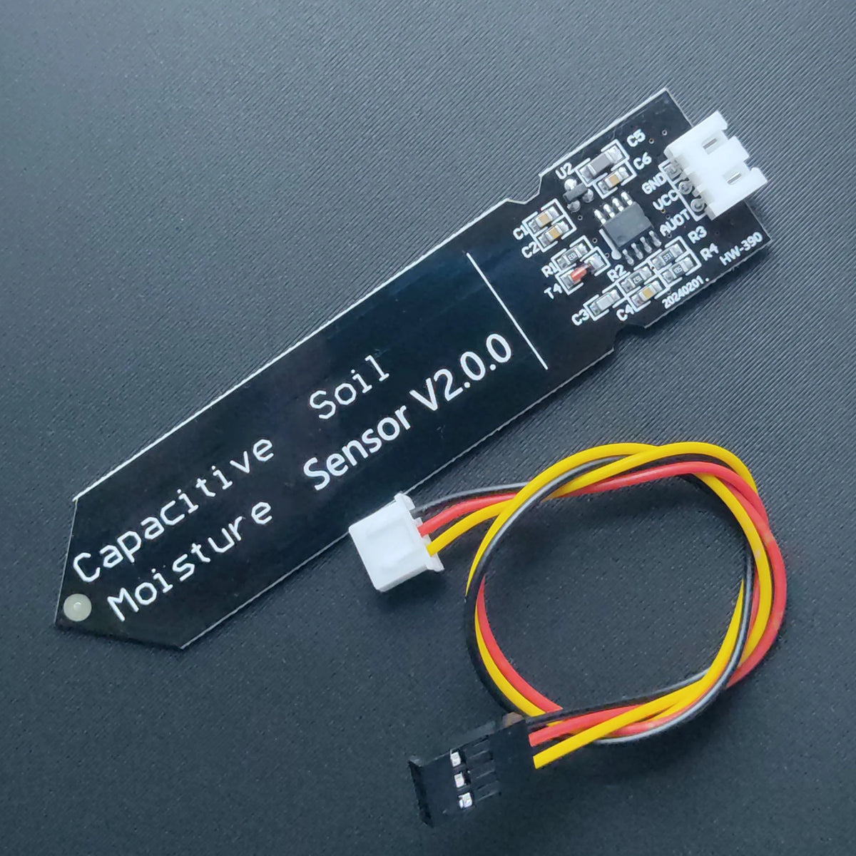
- one ADCAnalog-to-Digital Converter - converts analog voltages into digital values that microcontrollers can read.input for the Capacitive Soil Moisture SensorMeasures soil humidity via capacitance change instead of resistance. Corrosion-resistant and provides analog voltage proportional to moisture.
 ,
, - one PWMPulse Width Modulation - controls average power by switching rapidly. The duty cycle determines the effective output.output for the MOSFETMetal-Oxide-Semiconductor Field-Effect Transistor - an electronic power switch. Logic-level MOSFETs can be driven directly from GPIO pins.gate,
- one LEDA light-emitting diode used frequently as a status indicator in electronic devices.used as a status indicator.
Pinout
| Function | Raspberry Pi Pico Pin | Notes |
|---|---|---|
| Soil sensor analog OUT | GPIO26 (ADC Analog-to-Digital Converter - converts analog voltages into digital values that microcontrollers can read. ) | Higher reading = drier soil |
| Valve PWM (MOSFET gate) | GPIO0 | Logic-level PWM Pulse Width Modulation - controls average power by switching rapidly. The duty cycle determines the effective output. (3.3 V) |
| RGB LED data | GPIO25 | On-board LED A light-emitting diode used frequently as a status indicator in electronic devices. LED |
| 5 V input | USB VBUS | Wall USB power supply only |
| Ground | GND Ground - the common electrical reference point in a circuit. | Common reference for sensor, valve and controller |
Typical wiring
Soil moisture sensor
- VCC → 3.3 V or 5 V (according to sensor rating)
- GND → GND
- OUT → GPIO0 (ADCAnalog-to-Digital Converter - converts analog voltages into digital values that microcontrollers can read.)
The firmware assumes higher ADC
Valve / pump via MOSFETMetal-Oxide-Semiconductor Field-Effect Transistor - an electronic power switch. Logic-level MOSFETs can be driven directly from GPIO pins.
- Valve or pump positive → 5-12 V supply (directly or from a DCDirect Current - electric current flowing in one direction, common in batteries and embedded devices.-DCDirect Current - electric current flowing in one direction, common in batteries and embedded devices.step-up module)
- Valve or pump negative → MOSFETMetal-Oxide-Semiconductor Field-Effect Transistor - an electronic power switch. Logic-level MOSFETs can be driven directly from GPIO pins.drain
- MOSFETMetal-Oxide-Semiconductor Field-Effect Transistor - an electronic power switch. Logic-level MOSFETs can be driven directly from GPIO pins.source → GND
- MOSFETMetal-Oxide-Semiconductor Field-Effect Transistor - an electronic power switch. Logic-level MOSFETs can be driven directly from GPIO pins.gate → GPIO0 (optional 100-220 Ω series resistor in the gate line)
If the load is inductive (pump, solenoid valve), add a Flyback Diode
Power topology
- The ESP32A low-cost, low-power system on a chip (SoC) with integrated Wi-Fi and dual-mode Bluetooth.-C3 is powered from a 5 V USB wall charger.
- If a separate higher-voltage supply is used for the valve (e.g. a 12 V brick or step-up), all grounds must be tied together.
Safety notes
⚠️ Use only a wall USB power supply Do not power this project from a PC, laptop, TV, or monitor USB port. The valve or pump can draw more current than those ports are designed for.
💧 Keep electronics above water The tank and plumbing can eventually leak. Place the electronics box higher than the maximum water level and route cables with drip loops where practical.
⚡ Protective components Always use a Flyback Diode
A diode placed across inductive loads like valves or pumps to absorb voltage spikes when current is interrupted.on inductive loads and consider adding a fuse on the valve/pump supply line for extra safety.